
4-Wire Load Cell (1/5/10/20/200kg) with HX711 and Arduino

|
Written by Indrek Luuk
|


Table of content:
- Required Components.
- Video Tutorial.
- Verify Your Load Cell Wires.
- Attaching the Load Cell between Two Plates.
- Wiring the Load Cell to the HX711 Module and Arduino.
- Arduino Code to Read Weight Value from the HX711 Module.
- Testing the Scale.

https://circuitjournal.com/50kg-load-cells-with-HX711
You can buy relatively cheap four-wire load cells from Banggood, eBay, or Aliexpress.
They come with a wide variety of weight ranges, starting from one kilogram up to a couple of hundred kilograms.
The easiest way to get a weigh reading from these to an Arduino is to use the HX711 amplifier module.

It reads the tiny voltage change inside the load cell and turns it into a 24bit digital numeric value that can be interpreted by the Arduino as a weight value.
Required Components.


Disclosure: Bear in mind that some of the links in this post are affiliate links and if you go through them to make a purchase I will earn a commission. Keep in mind that I link these companies and their products because of their quality and not because of the commission I receive from your purchases. The decision is yours, and whether or not you decide to buy something is completely up to you.
Video Tutorial.
A step-by-step guide in video form.
Verify Your Load Cell Wires.
My load cell has red, black, green, and white wires.

Each wire connects to a corner of the Wheatstone bridge that is embedded into the load cell.

The first thing you need to do is to identify the opposing corners of the Wheatstone bridge. You can do that with a multimeter by measuring the resistance between the wires.
In my case, the opposing wires are red-black pair and green-white pair. The resistance between both of those pairs is about 1k ohm.


If I measured between any other combination of wires, then I got 750 to 850 ohms between them.


One of the pairs will be power wires, and the other one will be measurement wries. It doesn't matter which, but to follow the more conventional color scheme, we will pick red-black for power and white-green for measurement.
Attaching the Load Cell between Two Plates.
You need to create a strain between the opposing ends of the load cell.

The easiest way to do that is to attach it between two boards. The bottom board holds your home-made scale in place, and the top board is the weighing plate. Make sure you put some spacers between the board and the load cell, so there is room for deformation.

When you apply force to the load cell, two of the strain gauges will compress (red) while the other two will stretch (blue).

I didn't have suitable boards available, so I 3D printed this base frame and weighing plate. The 3D printed components can not handle the 20kg weight that this load cell is rated for, but it is strong enough for my experiments.

The load cell has an arrow sticker that indicates the direction for the force. You need to attach the weighing plate on top of it so that the arrow points down.
Then I connected the other end to the base structure.


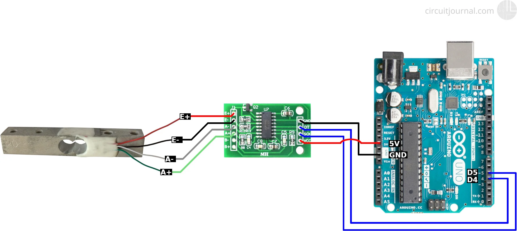
Wiring the Load Cell to the HX711 Module and Arduino
I am assuming that you have the same wire configuration as I have. One diagonal of the Wheatstone bridge is red-black, and the other one is green-white. If you have some different color variations, then you have to take that into consideration while following these steps.
I am doing my experiments with a 20 kg load cell, but the same principles apply for other types of four-wire load cells.
1. Connect the red wire to the E+ and the black wire to the E- output of the HX711 module.
We chose the red and black wire pair to be the power wires of the load cell. E+ and E- are the sensor power outputs of the HX711 module.
The polarity doesn't matter. We picked red to be the positive side and black to be the negative side to make it follow a common convention. Switching up red and black will only invert the calibration parameter in the software.
2. Connect the green wire to the A+ and the white one to the A- inputs of the HX711 module.
A+ and A- are the measurement inputs of the HX711 module. Like with the power wires, the polarity is not important. You just need to recalibrate in the software if you switch them up.
3. Connect the GND of the HX711 module to the Arduino GND and VCC to the Arduino 5V pin.
HX711 also works with 3.3V. If you have some other microcontroller that runs on 3.3V, you can use 3.3V instead of 5V.
4. Connect the DT and SCK of the HX711 module to any of the Arduino digital IO pins.
In the schematic, I used pins 4 and 5, since those are the default pins for the examples of the "HX711_ADC" library.
If you want to use interrupts to update scale data, then you should connect the DT output to an interrupt enabled pin of the Arduino. For Uno/Nano, those are pins 2 and 3.
Arduino Code to Read Weight Value from the HX711 Module.
Click on the green "Clone or download" button and then "Download ZIP."
Extract the downloaded ZIP file and move it into your Arduino "libraries" folder.
C:\Users\<username>\Documents\Arduino\libraries
/Users/<username>/Documents/Arduino/libraries
2. Open the Calibration example that came with the "HX711_ADC" library.
3. Load the example code to your Arduino.
It should work without any modifications if you connected the DT output of the HX711 module to the Arduino pin 4, and SCK to the Arduino pin 5.
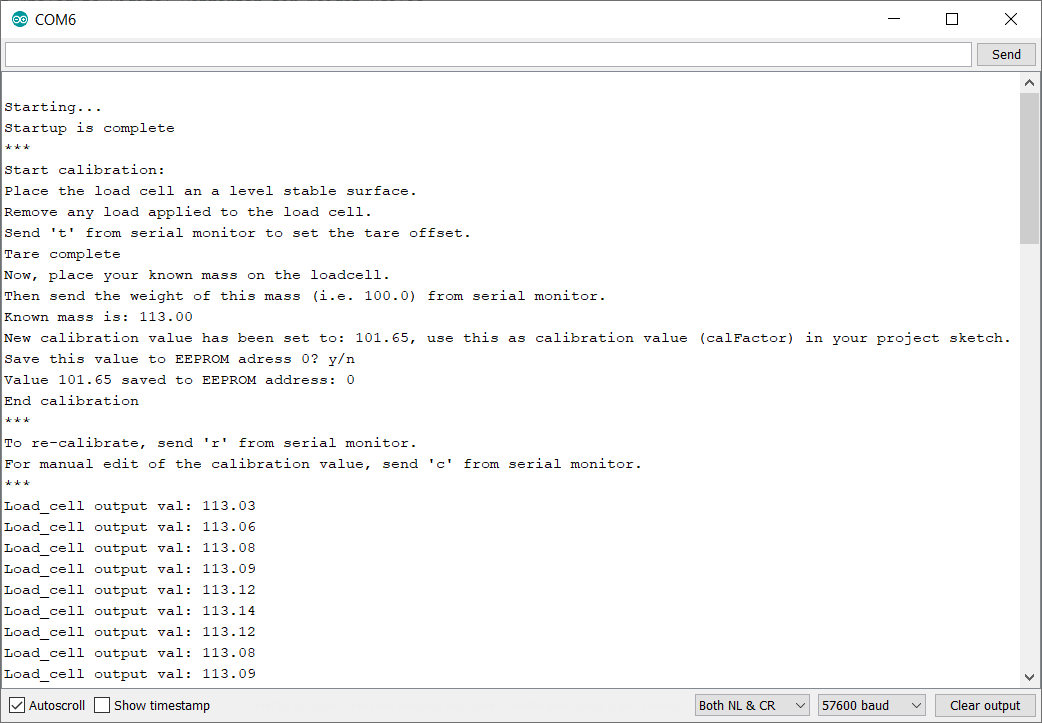
4. Open the Arduino Serial Monitor.
Follow the directions in the terminal window. It asks you to put a known mass onto the load cells and then enter the weight of that item. This process calibrates your scale.
I used an iPhone 5, which is 113 grams.
Then it starts outputting the current weight value on the scale.
Testing the Scale.
I have a kitchen scale to compare results - this glass of water weight about 490 grams.


