
Programming ESP-12E / ESP-12F / NodeMCU With Arduino IDE

|
Written by Indrek Luuk
|
The ESP-12E and ESP-12F are ESP8266 boards. ESP8266 is a low-cost WiFi-enabled microchip.
This article will explain how to prepare your Arduino IDE to upload sketches into the ESP8266 microcontroller and connect to an ESP-12E / ESP-12F board over USB.
It is also possible to upload Arduino Sketches to ESP8266 over Wi-Fi. You can do that after you have successfully established the USB connection since the program running on the microcontroller needs to be able to receive code updates over the network.

|
My article about programming the ESP-12E / ESP-12F / NodeMCU over the Wi-Fi connection: |
I have tested all the connections and external modules mentioned in this article with the ESP-12E, ESP-12F, and NodeMCU boards.
It will probably also work with the older ESP-07 AND ESP-12 (without any letters), but I haven't experimented with those myself.


Table of content:
- 1. Preparing Your Arduino IDE for ESP8266
- 2. Arduino Code
- 3. Connecting to ESP-12E/ESP-12F Board Via USB
- 3.1. Connecting a USB-to-Serial Adapter to ESP-12E/ESP-12F
- 3.2. Uploading Arduino Code to ESP-12E/ESP-12F With a Programmer Board
- 3.3. Uploading Arduino Code to ESP-12E/ESP-12F With a Witty Cloud Development Board
- 3.4. Uploading Arduino Code to NodeMCU
- 3.5. Uploading Arduino Code to ESP-12E/ESP-12F With a NodeMCU Board
Disclosure: Bear in mind that some of the links in this post are affiliate links and if you go through them to make a purchase I will earn a commission. Keep in mind that I link these companies and their products because of their quality and not because of the commission I receive from your purchases. The decision is yours, and whether or not you decide to buy something is completely up to you.
ESP Modules:


Video tutorial:
1. Preparing Your Arduino IDE for ESP8266
Then we need to add the ESP8266 to the Boards list.
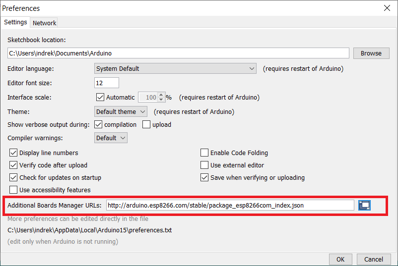
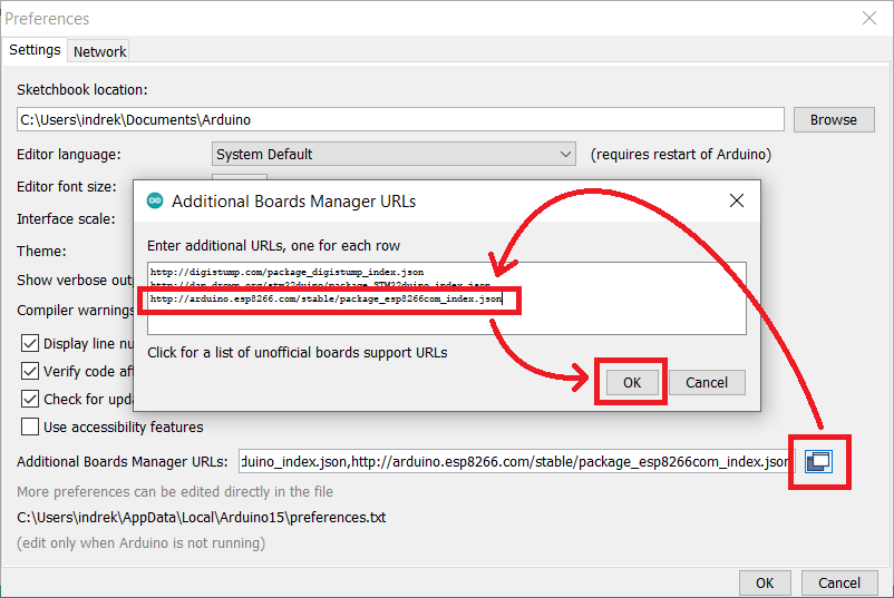
If you already have some existing board URLs, click on the little sub-form button after the field and add the ESP8266 board URL to the end of the list.
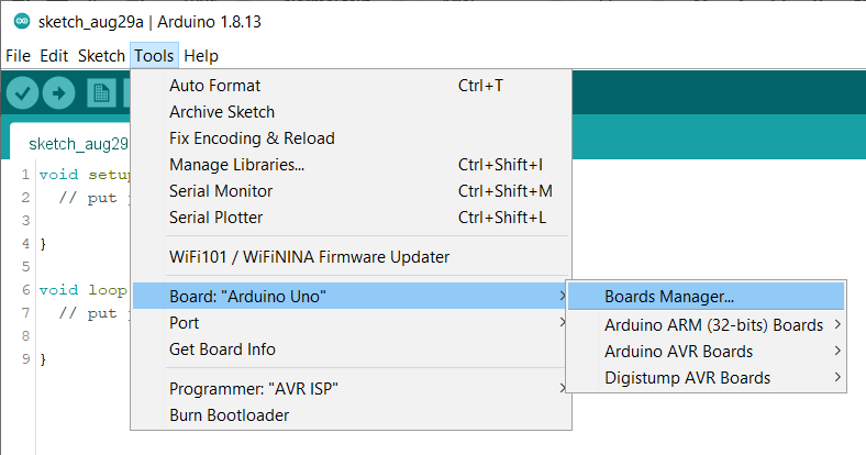
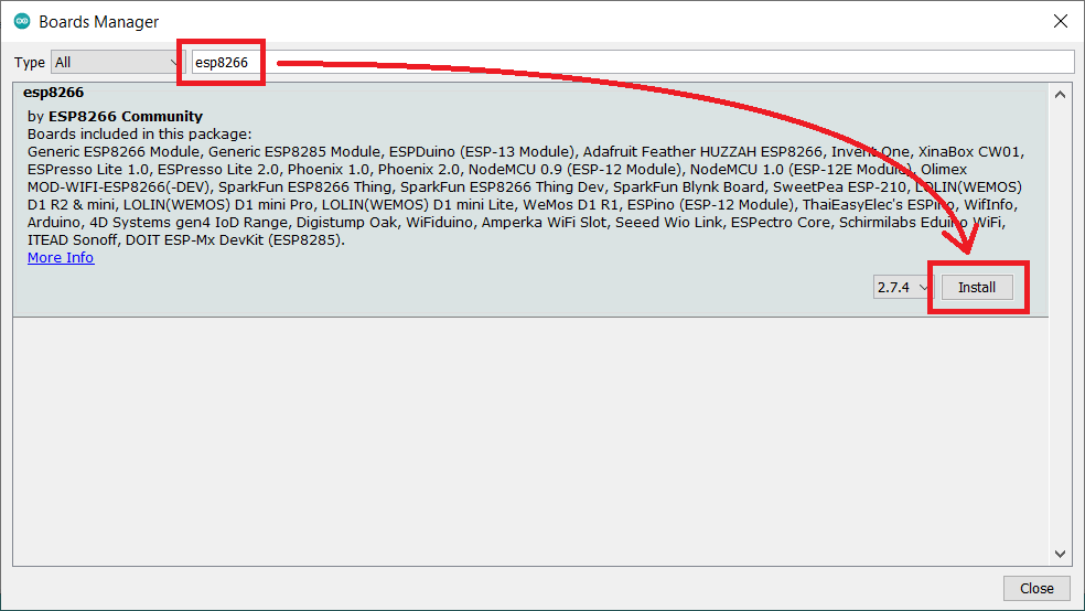
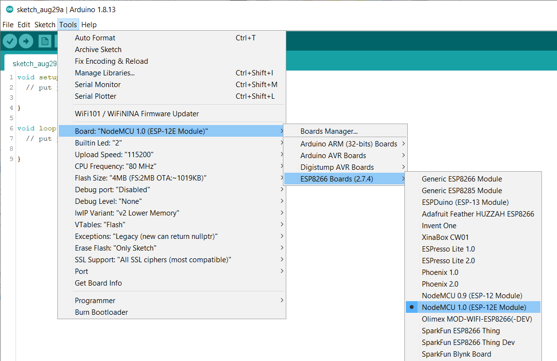
Now you should see the "ESP8266 Boards" sub-menu under Boards.
Select "NodeMCU 1.0 (ESP-12E Module)" (it works for both ESP-12E and ESP-12F).
2. Arduino Code
// the setup function runs once when you press reset or power the board
void setup() {
  // initialize digital pin LED_BUILTIN as an output.
  pinMode(LED_BUILTIN, OUTPUT);
}

// the loop function runs over and over again forever
void loop() {
  digitalWrite(LED_BUILTIN, HIGH);   // turn the LED on (HIGH is the voltage level)
  delay(1000);                       // wait for a second
  digitalWrite(LED_BUILTIN, LOW);    // turn the LED off by making the voltage LOW
  delay(1000);                       // wait for a second
}
The next step is to connect the ESP-12E / ESP-12F module physically to your computer.
3. Connecting to ESP-12E/ESP-12F Board Via USB
There are a couple of different options depending on the board type and the tools you have.
3.1. Connecting a USB-to-Serial Adapter to ESP-12E/ESP-12F
If you have a dedicated USB-to-serial adapter board, you can use it to program the ESP-12E / ESP-12F.

Required components:
-
(the red board in the image is functionally the same as the black one in the schematic)


Optionally you can solder the ESP module onto an adapter board:

IMPORTANT! The 3.3V power output of the USB-to-serial adapter is too weak to run the ESP-12E / ESP-12F module. You need to use an external 3.3V power source.
Full (automatic reset) - if your USB-to-serial adapter has RTS output available, you can wire up fully automatic connections. It means that you can click "Upload" in the Arduino IDE, then it will automatically reset the ESP module and enter into programming mode. After a successful upload, it will reset again, and your program will run.
Simple (manual reset) - some simpler adapter modules do not bring the RTS signal out as an accessible output (even though the USB-to-serial chip on the board probably has it). In that case, you need to connect the GPIO_0 pin to the ground and then reset the device manually. After successful upload, you need to disconnect the GPIO_0 pin from the ground and reset again.
The ESP8266 has three different boot modes selected by the state of GPIO_15, GPIO_0, and GPIO_2 at start-up.
| MODE | GPIO_15 | GPIO_0 | GPIO_2 |
|---|---|---|---|
| SDIO (Boot SD Card) | 1 | x | x |
| UART (Upload Code) | 0 | 0 | x or 1 |
| FLASH (Normal Running) | 0 | x or 1 | x or 1 |
1. SDIO (Boot SD Card) - this mode is irrelevant for us. Since we never want to use it, we can connect the GPIO_15 to GND via a 10k resistor.
Note: technically, you could also connect the GPIO_15 directly to the ground without a resistor. But if you accidentally define GPIO_15 as output in your Arduino code and now set the pin to HIGH, it will create a short circuit and probably damage the microcontroller.
2. UART (Upload Code) - we need to activate this mode to upload new code. Both GPIO_15 and GPIO_0 pin need to be pulled down to the ground at the boot-up time. GPIO_2 may be left unconnected (or pulled up to 3.3V).
3. FLASH (Normal Running) - this mode is for running your code. GPIO_15 must be pulled to the ground, and GPIO_0 and GPIO_2 must be left either floating or pulled up to 3.3V.
The "chip enable" (EN/CH_PD) pin has to be pulled up to 3.3V. Otherwise, the ESP8266 will not run
You can make your life easier by soldering the module onto an adapter board.
It has the EN/CH_PD pull-up and GPIO_15 pull-down resistors pre-soldered. It also makes the ESP-12E/ESP-12F breadboard and jumper wire friendly.

If your USB-to-serial adapter has a CH340 USB-to-serial chip on it,
you may need to download and install the CH340 drivers for your operating system:
https://sparks.gogo.co.nz/ch340.html
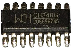
If it has an FTDI or CP2102 USB-to-serial chip, the drivers should be included with your operating system.
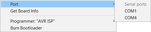
Now you can plug a USB cable into the USB-to-serial adapter, and it should show up in Arduino IDE.
Full (automatic reset)
If you have already opened the "Blink" example (File->Examples->01.Basic->Blink), you can now click on the "Upload" button.
After a successful upload, you should see a blue LED blinking on the board.
Simple (manual reset)
If you made the simple connections, connect the GPIO_0 pin to the ground and reset the ESP-12E / ESP-12F module. Now it should be in programming mode.
If you have already opened the "Blink" example (File->Examples->01.Basic->Blink), you can now click on the "Upload" button.
After the upload has finished, you need to disconnect the GPIO_0 pin from the ground and reset the device again.
After a successful upload, you should see a blue LED blinking on the board.
3.2. Uploading Arduino Code to ESP-12E/ESP-12F With a Programmer Board
The easiest way to load your sketch into a plain ESP-12E / ESP-12F is to buy a programmer board. These are solderless, and the ESP module snaps onto it.
There are different types available. I have these two:


These programmer boards cost from 10 to 20 USD, but the good news is that you need to buy only one.
Required components:

If your programmer board has a CH340 USB-to-serial chip on it,
you may need to download and install the CH340 drivers for your operating system:
https://sparks.gogo.co.nz/ch340.html
If it has an FTDI or CP2102 USB-to-serial chip, the drivers should be included with your operating system.
Now you can plug a USB cable into it, and it should show up in Arduino IDE.
If you have already opened the "Blink" example (File->Examples->01.Basic->Blink), you can now click on the "Upload" button.
After a successful upload, you should see a blue LED blinking on the board.
Note! The programmer board's biggest downside is that you can't use it after soldering the ESP module to your circuit.
One workaround is to do later updates over the Wi-Fi connection.
|
|
My article about programming the ESP-12E / ESP-12F / NodeMCU over the Wi-Fi connection: |
3.3. Uploading Arduino Code to ESP-12E/ESP-12F With a Witty Cloud Development Board
The plain ESP-12E / ESP-12F module is not breadboard-friendly. So you most likely want to solder it onto an adapter module.


The footprint of this adapter board matches the Witty Cloud Development Board.

If you buy one set of the Witty Cloud Development Board, you will get a USB board + an ESP-12F board with some extra sensors.

You can use the Witty USB board to program your plain ESP-12E / ESP-12F soldered onto the adapter board.
Required components:


IMPORTANT! You can't plug it into the Witty USB board immediately! The white adapter board expects VCC to be regulated 3.3V, but the Witty board gives out 5V from the USB.
You need to remove the 0 Ohm resistor that connects the adapter board's VCC directly to the VCC of the ESP8266.


Then solder a 3.3V voltage regulator to the back of the white adapter board. It has a footprint for it. I have used an HT7333-A.
IMPORTANT! Please note that the middle pin of the regulator footprint is Vin. Some voltage regulators have the middle pin as Vout (like AMS1117) - you can not use these.


Unfortunately the footprint of the HT7333-A chip is a little smaller than the footprint on the board. But you can still solder it onto the PCB.
The input of the HT7333-A can be 3.5V to 12V. It means that now you can power the board with any voltage source in the range of 3.5V to 12V.
After these modifications, you can plug your ESP-12E / ESP-12F on top of the Witty Cloud USB board.

If your board has a CH340 USB-to-serial chip on it,
you may need to download and install the CH340 drivers for your operating system:
https://sparks.gogo.co.nz/ch340.html
If it has an FTDI or CP2102 USB-to-serial chip, the drivers should be included with your operating system.
Now you can plug a USB cable into it, and it should show up in Arduino IDE.
If you have already opened the "Blink" example (File->Examples->01.Basic->Blink), you can now click on the "Upload" button.
After a successful upload, you should see a blue LED blinking on the board.
3.4. Uploading Arduino Code to NodeMCU
NodeMCU is an ESP-12E or ESP-12F based board with added power and serial circuitry. It is a bit more expensive than a plain ESP-12E or ESP-12F, but it is easier to get started.
Required components:
If your NodeMCU board has a CH340 USB-to-serial chip on it,
you may need to download and install the CH340 drivers for your operating system:
https://sparks.gogo.co.nz/ch340.html
If it has an FTDI or CP2102 USB-to-serial chip, the drivers should be included with your operating system.
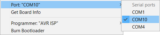
Connecting a USB cable to the NodeMCU module is enough. It should show up in the "Tools->Port" menu.
If you have already opened the "Blink" example (File->Examples->01.Basic->Blink), you can now click on the "Upload" button.
After a successful upload, you should see a blue LED blinking on the board.
3.5. Uploading Arduino Code to ESP-12E/ESP-12F With a NodeMCU Board
You can use a NodeMCU board to upload your Arduino code to a plain ESP-12E / ESP-12F.

Required components:
NodeMCU is an ESP-12E or ESP-12F based board with added power and serial circuitry. It means that if you disable the module soldered onto the NodeMCU board, you can attach an external ESP module instead of it.
1. To disable the onboard ESP chip, you need to connect the EN pin on the NodeMCU board to GND.
2. Connect RX to RX and TX to TX
3. Connect RESET to RESET and D3 (it maps to GPIO_0) of the NodeMCU board to GPIO_0.
These connections ensure that the external ESP module goes properly into programming mode when you click "Upload" in the Arduino IDE.
4. Pull the EN/CH_PD of the external ESP module to 3.3V and GPIO_15 to GND.
5. And finally, connect the 3.3V pin of the NodeMCU module to VCC and GND to GND.
If your NodeMCU board has a CH340 USB-to-serial chip on it,
you may need to download and install the CH340 drivers for your operating system:
https://sparks.gogo.co.nz/ch340.html
If it has an FTDI or CP2102 USB-to-serial chip, the drivers should be included with your operating system.
Now you can plug a USB cable into the NodeMCU. It should show up in the "Tools->Port" menu.
If you have already opened the "Blink" example (File->Examples->01.Basic->Blink), you can now click on the "Upload" button.
The code is uploaded into the external module since the onboard soldered chip is disabled.
After a successful upload, you should see a blue LED blinking on the board.

