
How to Use OV7670 Camera with Arduino and a Tiny Screen

|
Written by Indrek Luuk
|
This article is a step-by-step guide for setting up all the necessary connections to stream images from the OV7670 camera module to a tiny 1.8 inch TFT screen.
You can easily follow along by making all the connections on a breadboard. I have also added some mid-point checks to verify if everything is connected correctly thus far.
After completing my tutorial, you should end up with something like this:

This video clip is a short demo of the camera in action. In this video, you see a PCB version of the same circuit.

https://circuitjournal.com/arduino-OV7670-to-pc
Required Components


[OPTIONAL] Oscilloscope I used to get it all working
If you can't get the image to show up, it is much easier to track down issues with an oscilloscope. Often the problem is the shape of the clock signals. With an oscilloscope, you can see which wire is not working properly and then try to find a solution to fix it.

Disclosure: Bear in mind that some of the links in this post are affiliate links and if you go through them to make a purchase I will earn a commission. Keep in mind that I link these companies and their products because of their quality and not because of the commission I receive from your purchases. The decision is yours, and whether or not you decide to buy something is completely up to you.
Video Tutorial
A step-by-step guide in video form. It has the same schematics I am using in this article.
1. Preparing the Screen
Short the J1 connector on the back of the screen. Then the VCC pin of the display can be connected to the 3.3V pin of the Arduino board.

When I started experimenting with the 1.8 inch TFT, I had faint vertical stripes going across the screen. By default, the screen is configured to be powered by 5V, but internally it operates at 3.3V levels. I was able to get rid of those ghosting lines by using 3.3V data signals (with voltage dividers) and switching the power input over to 3.3V.

2. Connecting the 1.8 Inch TFT to Arduino
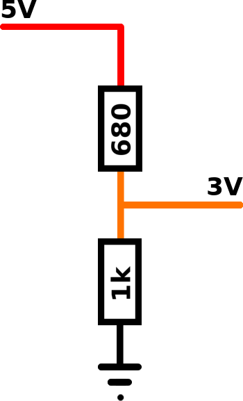
The input pins of the 1.8 inch TFT screen are not 5V tolerant. You have to convert the Arduino 5V signals to 3V. The easiest way to achieve that is to put voltage dividers on the signal wires.
The full schematic for the connections looks like a rat's nest and is a bit hard to follow. I have divided it into steps to make it easier.
Click on the buttons to switch between the steps of the schematic.

Add a Voltage divider to every connection made in steps 1 to 5.
3. Test the Screen Connections
You should test the screen wiring before continuing with connecting the camera.
1. Download the code of my LiveOV7670 project:
https://github.com/indrekluuk/LiveOV7670
Click on the green "Code" button and then "Download ZIP."

Extract the downloaded ZIP file.
2. Copy the two libraries "LiveOV7670Library" and "Adafruit_GFX_Library" from "src/lib" to your Arduino "libraries" folder
C:\Users\<username>\Documents\Arduino\libraries
/Users/<username>/Documents/Arduino/libraries
"LiveOV7670Library" contains the code that communicates with the OV7670 camera module.
"Adafruit_GFX_Library" is a dependency of the "Adafruit-ST7735" screen library. In this project, I am using a modified version of the Adafruit's ST7735 library – "Adafruit_ST7735_mod.h" and "Adafruit_ST7735_mod.cpp" in the "src/LiveOV7670" folder. The original was too slow. To get it faster, I had to cut some corners in the method that sends pixel data to the display.
3. Open "src/LiveOV7670/LiveOV7670.ino" and load it into your Arduino.
This project takes advantage of some of the C++11 features. C++11 is enabled by default since Arduino IDE version 1.6.6. If, for some reason, you have an older version, then you should either upgrade or enable C++11 in the Arduino IDE configuration file.
4. If everything is connected correctly, then the screen should flash red.

The solid red color means that the code wasn't able to detect the camera module. But since we see the color, we can be sure that the screen wiring is OK.
If you do not see the red image, then check your wiring, and make sure that you have shorted the J1 connector on the back of the screen.
4. First Part of the Camera Connections – Power It Up
We will do the camera wiring in two phases. In this chapter, we are going to make all the necessary connections to get the camera running and configured by the Arduino.
Click on the buttons to switch between the steps of the schematic.

5. Validate That the Camera is Running
This is the second test before we get to the actual images from the camera.
When you start the Arduino again, then it should flash a green screen. This means that the LiveOV7670 library was able to detect and configure the camera successfully.

You can't see any images yet since the pixel data pins are not connected.
If you still see the red screen, then check the wiring. Make sure that the XCLK wire isn't too long. The square wave of the input clock signal to the camera may become too deformed for it to operate correctly.
6. Second Part of the Camera Connections – Pixel Data Pins
Now we can finish the camera wiring by connecting pixel data inputs. Pixels are streamed from the camera one byte at the time. Each pixel consists of two bytes that are read sequentially.
Click on the buttons to switch between the steps of the schematic.

7. Done!
Now you can power up your Arduino again. It starts with a green image like in the previous test. Then you should see a live video streamed from the camera to the display.

