SIMPLIFIED! How to Use OV7670 Camera with Arduino.

|
Written by Indrek Luuk
|
This article is a step-by-step guide for setting up all the necessary connections to stream images from the OV7670 camera module to your computer.
You can also watch the same tutorial as a Youtube video:
I have made an easy-to-install "ArduImageCapture" plug-in for Arduino IDE that captures images on the computers' side. The plug-in works on all platforms that can run Arduino IDE (Windows, Mac, Linux).
After installing "ArduImageCapture," you can easily follow along by making all the connections on a breadboard. I have also added some mid-point checks to verify if everything is connected correctly thus far.


https://circuitjournal.com/arduino-ov7670-10fps
Required Components


[OPTIONAL] Oscilloscope I used to get it all working
If you can't get the image to show up, it is much easier to track down issues with an oscilloscope. Often the problem is the shape of the clock signals. With an oscilloscope, you can see which wire is not working properly and then try to find a solution to fix it.

Disclosure: Bear in mind that some of the links in this post are affiliate links and if you go through them to make a purchase I will earn a commission. Keep in mind that I link these companies and their products because of their quality and not because of the commission I receive from your purchases. The decision is yours, and whether or not you decide to buy something is completely up to you.
Installing "ArduImageCapture" Plug-In
https://github.com/indrekluuk/ArduImageCapture
Extract the zip file and copy the "ArduImageCapture" folder into your Arduino "tools" folder next to the Arduino "libraries" folder. If the "tools" folder doesn't exist, then you can create it yourself.
C:\Users\<username>\Documents\Arduino\tools
/Users/<username>/Documents/Arduino/tools

Now run/restart your Arduino IDE, and you should see "ArduImageCapture" under the "Tools" menu.

Arduino Code
1. Download the code of my LiveOV7670 project:
https://github.com/indrekluuk/LiveOV7670
Click on the green "Code" button and then "Download ZIP."

Extract the downloaded ZIP file.
2. Copy the two libraries "LiveOV7670Library" and "Adafruit_GFX_Library" from "src/lib" to your Arduino "libraries" folder.
C:\Users\<username>\Documents\Arduino\libraries
/Users/<username>/Documents/Arduino/libraries
"LiveOV7670Library" contains the code that communicates with the OV7670 camera module.
"Adafruit_GFX_Library" is a dependency of the "Adafruit-ST7735" screen library. We aren't using any screens in this tutorial, but the dependency is still required for the LiveOV7670 sketch to compile.
3. Open "src/LiveOV7670/LiveOV7670.ino" with Arduino IDE.
This project takes advantage of some of the C++11 features. C++11 is enabled by default since Arduino IDE version 1.6.6. If you have an older version for some reason, you should either upgrade or enable C++11 in the Arduino IDE configuration file.
4. Switch to "EXAMPLE 3" in "setup.h".
Select "setup.h" tab and change the definition to:
#define EXAMPLE 3
"EXAMPLE 3" will activate the "ExampleUart.cpp". This is the code that sends images over the USB cable.
The default "EXAMPLE 1" tries to send the image to a tiny TFT screen.
https://circuitjournal.com/arduino-ov7670-10fps
5. Upload the code to your Arduino.
We can make the first test before connecting any wires.
Checkpoint 1
Open "ArduImageCapture." It should start listening to the serial port automatically. If not, select the correct COM port and click "Listen."
You should see a red image. This means that you have the correct code in your Arduino, but it couldn't detect the camera module.
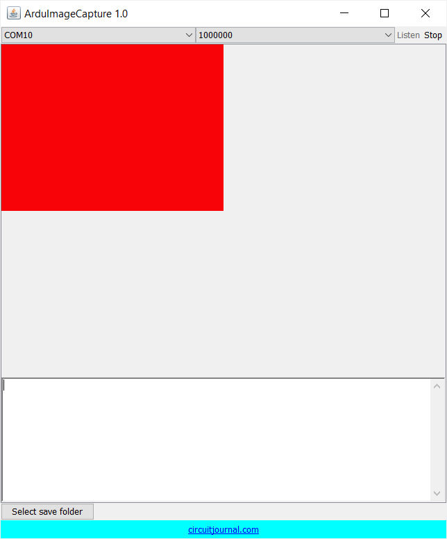
The default baud rate for the LiveOV7670 project is 1Mbit/sec (1000000) at 320x240 resolution. It works well if you have an Arduino clone with the CH340 serial chip and a Windows PC.
If you have a genuine Arduino with an FTDI serial chip or use a Mac, then you may see a scrambled line ends:
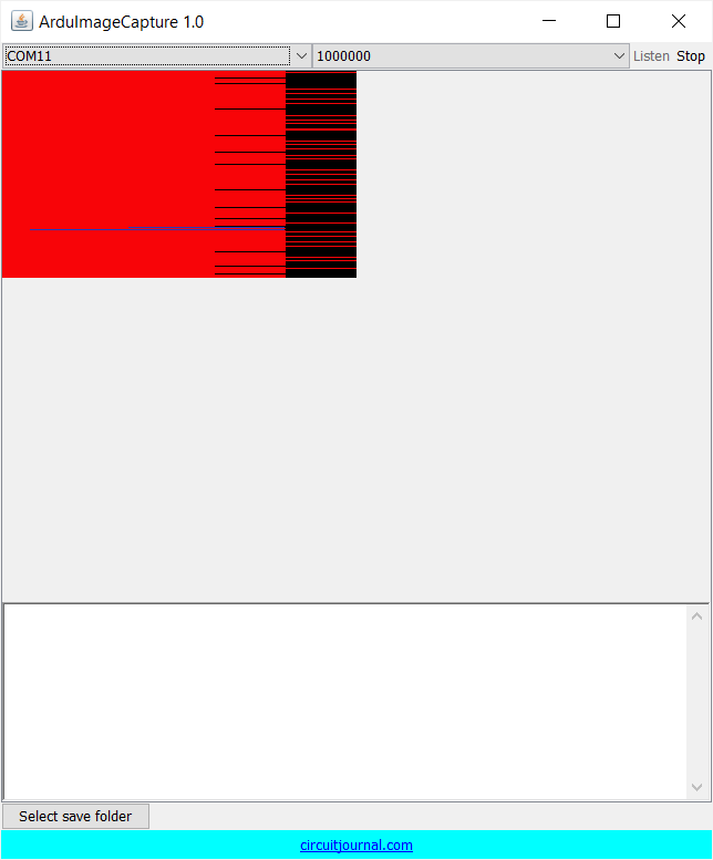
For some reason, a genuine Arduino with an FTDI serial chip will not work with a 1MBit/sec baud rate. So you need to reduce the speed to 115200 bit/sec.
Similar problem with Mac. For some reason, 1Mbit/sec doesn't work on Mac.
In those cases, select the "ExampleUart.cpp" tab and change the definition to:
#define UART_MODE 4
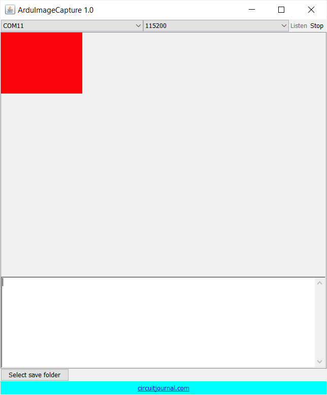
This lowers the resolution to 160x120 with a 115200 baud rate. (Unfortunately, 115200 is too slow to transfer higher resolution)
After uploading the code again, choose "115200" from the serial speed selection.
Now You should see this image:
First Part of the Camera Connections – Power It Up
We will do the camera wiring in two phases. In this chapter, we will make all the necessary connections to get the camera running and configured by the Arduino.
Click on the buttons to switch between the steps of the schematic.

Checkpoint 2
Let's validate that the Camera is Running. This is the second test before we get to the actual images from the camera.
Your wiring should look something like this:

When you start your Arduino again and open "ArduImageCapture," it should flash a green image. This means that the LiveOV7670 library was able to detect and configure the camera successfully.
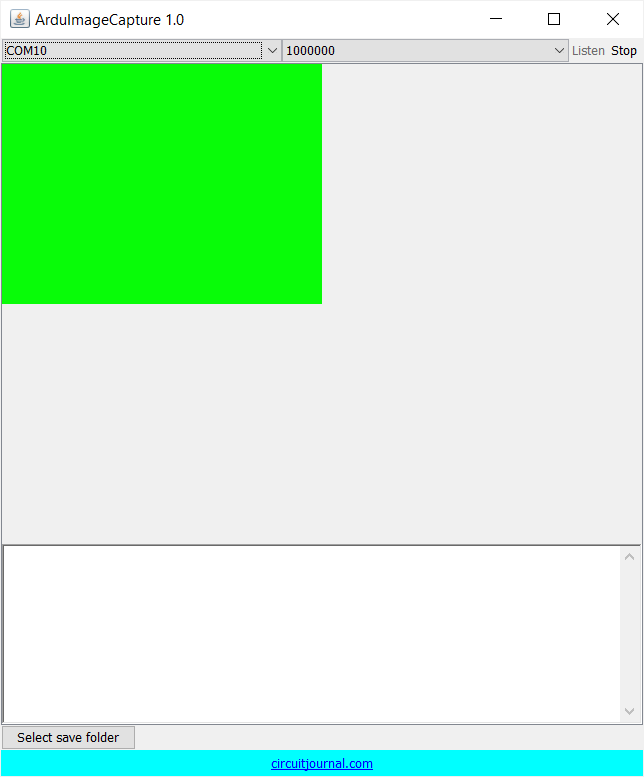
You can't see any images yet since the pixel data pins are not connected.
If you still see the red image, then check the wiring. Make sure that the XCLK wire isn't too long. The square wave of the input clock signal to the camera may become too deformed for it to operate correctly.
Second Part of the Camera Connections – Pixel Data Pins
Now we can finish the camera wiring by connecting pixel data inputs. Pixels are streamed from the camera one byte at a time. Each pixel consists of two bytes that are read sequentially.
Click on the buttons to switch between the steps of the schematic.

Done!
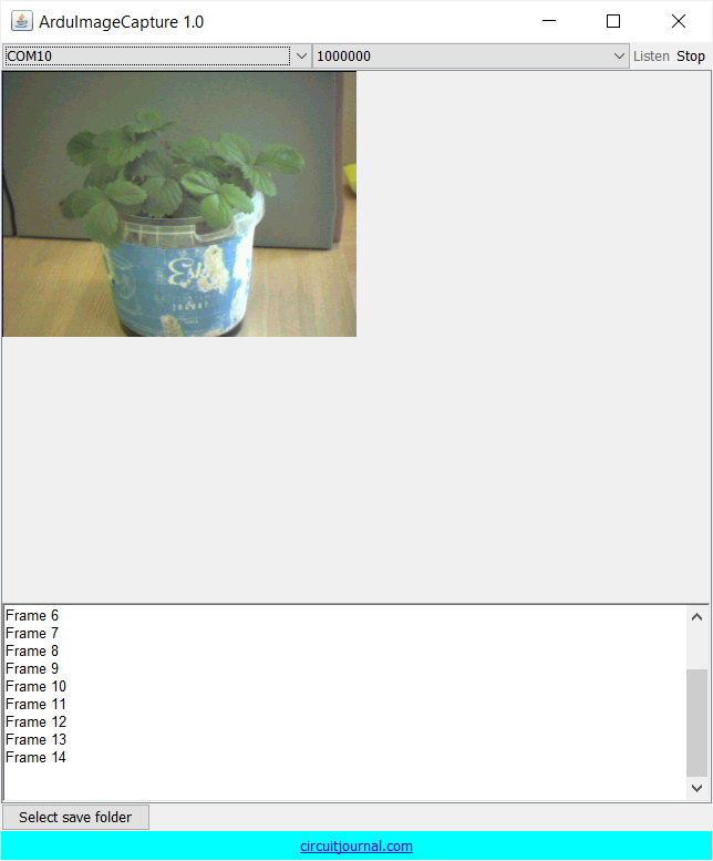
Now you can power up your Arduino and open "ArduImageCapture" again.

It starts with a green image like in the previous checkpoint, and then you should see a live video streaming from the camera.