How to Make Auto Power OFF Circuit with Arduino?

|
Written by Indrek Luuk
|
Table of content:
- Arduino Self Power OFF Circuit.
- How to Read the Power Button Status in Your Code?
- Can You Build a Self Power OFF Circuit with One MOSFET?
The charge of a battery is limited. It would be nice if your battery-powered device could power itself OFF if it has been idle for some time.
With a couple of MOSFETs and some resistors, you can create a circuit that makes it possible for your Arduino to use a Digital Output pin to shut itself OFF.
In this article, I am going to explain step-by-step how to make the connections. First, let's make the basic connections, and then optionally, we can add some wires to read the push button status in your Arduino code.
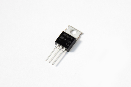
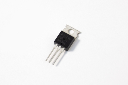
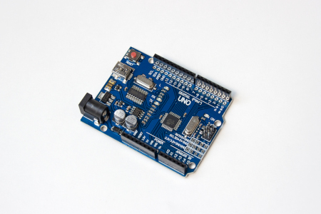
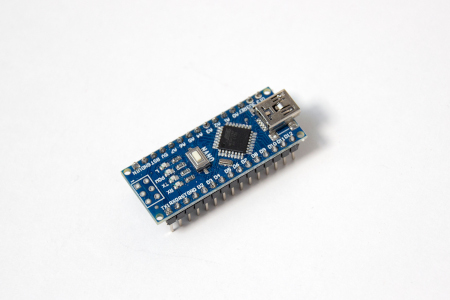
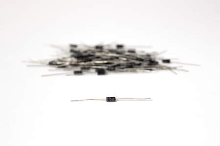
Required Components
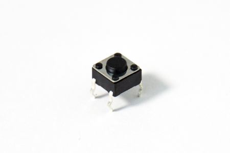
Optionally, if you want to read your power button status from a Digital Input pin you also need:
Disclosure: Bear in mind that some of the links in this post are affiliate links and if you go through them to make a purchase I will earn a commission. Keep in mind that I link these companies and their products because of their quality and not because of the commission I receive from your purchases. The decision is yours, and whether or not you decide to buy something is completely up to you.
Arduino Self Power OFF Circuit.

The power source has to be 7 to 12 volts. We are going to connect it to the Vin pin, and the on-board voltage regulator needs it to be at least 7V to work reliably.
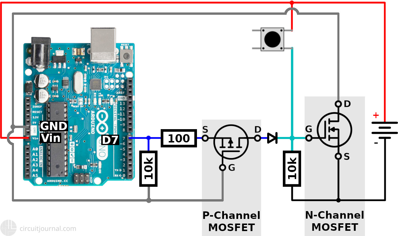
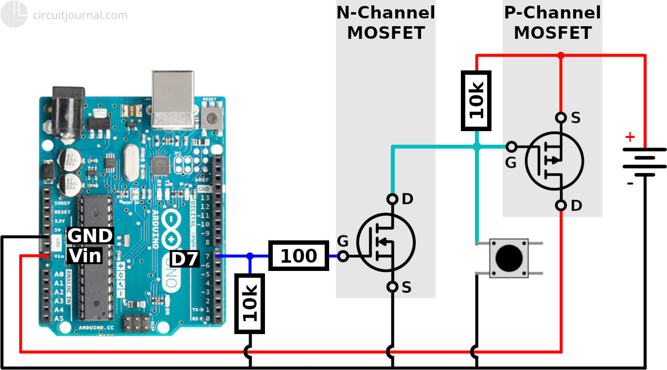
1. Connect the P-Channel MOSFET between the Arduino Vin pin and the positive output of the power source.
The Drain terminal goes to the Vin pin and the Source to the positive side of the power supply.
This MOSFET is the main power switch.
2. Connect the negative output of the power source to the Arduino GND pin.
3. Add a 10k pull-up resistor between the Gate and Source terminals of the P-Channel MOSFET.
The MOSFET will be in the OFF state if the voltage between Gate and Source is 0V. This pull-up resistor ensures that the power is switched OFF while neither the button or Arduino D7 pin is active.
4. Connect a push-button between the Gate and the GND.
Now you can try it. If you hold down the button, Arduino will turn ON. At this stage, it will turn OFF immediately when you release the button.
5. Put an N-Channel MOSFET between the Gate terminal of the P-Channel MOSFET and the GND.
The Drain terminal of the N-Channel MOSFET goes to the Gate of the P-Channel MOSFET. The Source of the N-Channel MOSFET to the GND.
This is the secondary MOSFET that acts as a switch for the Arduino output pin to pull down the Gate of the main power MOSFET.
6. Add a 10k resistor from the Gate of the N-Channel MOSFET to the GND.
This resistor ensures that the N-Channel MOSFET is turned OFF while Arduino is powered OFF.
7. Connect the Arduino digital output D7 pin to the N-Channel MOSFET's Gate via a 100-ohm resistor.
The 100-ohm resistor is necessary since the MOSFET will have a small internal capacitance. When you switch the digital output pin, it will start to charge/discharge, and it will create a current spike that can damage the Arduino Arduino pin, especially if you plan to do high-frequency switching.
The wiring part is now done. But if you try it now, it will still switch off immediately after you release the button.
8. Finally, you need to activate the Digital Output D7 to keep the power ON after the button is released.
void setup() {
  pinMode(7, OUTPUT);
  digitalWrite(7, HIGH);
}
When you power up the Arduino, it takes about two seconds for your code to run. It's the time that Arduino bootloader waits for a new program to be loaded to the controller.
This boot-up delay means that you have to hold the button for about two seconds. If you release it too early, then it will shut down immediately. If you keep it down a couple of seconds, then it will stay ON.
To shut down the Arduino from your code, you have to set Digital Output D7 to LOW.
This code will shut down the Arduino 5 seconds after start-up:
void loop() {
  delay(5000);
  digitalWrite(7, LOW);
}
How to Read the Power Button Status in Your Code?
You may want to read the power button status while the device is running. For example, if you also want to use it as the OFF button.
To make this possible, you have to modify the circuit a little.
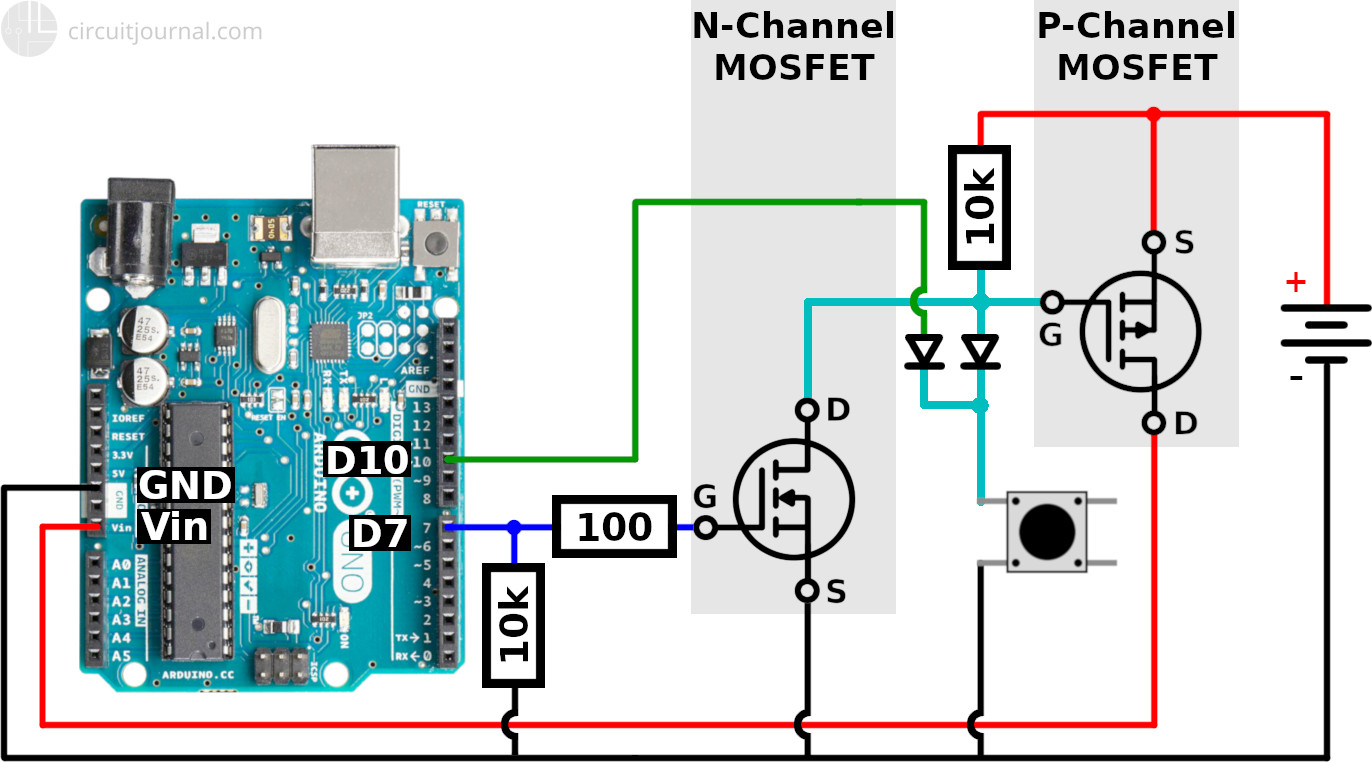
1. Add a diode between the Push Button and the Gate of the P-Channel MOSFET.
This diode is necessary to prevent the N-Channel MOSFET from pulling down the D10 signal if D7 is active. We only want the D10 pin to be pulled down by the button.
2. Add another diode to the Push Button in parallel to the first diode.
The second diode is to protect the D10 pin from the voltage coming from the power source. It can be 7 to 12 volts. Arduino pins are not designed to handle that.
3. Connect a wire from a Digital Input pin to the second diode.
4. Initialize the Digital Input D10 pin with INTERNAL_PULLUP.
void setup() {
  pinMode(10, INPUT_PULLUP)

  pinMode(7, OUTPUT);
  digitalWrite(7, HIGH);
}
Now, if the button is pressed then it will also pull down the signal from D10.
Below is an example program. After boot-up, it will start counting down from 5 seconds. If you press the button while it is running, the 5-second timer will reset, and the on-board LED will blink. If you release the button, it will continue counting down, and it will shut itself down if the time is up.
long shutdownTimer = 0;

void setup() {
  // initialize pin 13 as output
  // to blink the on-board LED
  pinMode(13, OUTPUT);

  // initialize the button status pin
  pinMode(10, INPUT_PULLUP);

  // hold the power mosfet ON
  pinMode(7, OUTPUT);
  digitalWrite(7, HIGH);
}

void loop() {
  // wait for the shut-down timer
  while (millis() - shutdownTimer < 5000) {
    // if the button is pressed
    // (pin 10 is pulled to ground)
    // then extend shutdownTimer
    // and blink the on-board LED
    if (!digitalRead(10)) {
      shutdownTimer = millis();
      blinkLed();
    }
  }
  // when the time is up then shut it down
  digitalWrite(7, LOW);
  // give it time to shut down
  delay(1000);
}

void blinkLed() {
    digitalWrite(13, HIGH);
    delay(200);
    digitalWrite(13, LOW);
    delay(200);
}
Can You Build a Self Power OFF Circuit with One MOSFET?
No.
You can't use a single MOSFET since you will get a current leakage through the pull-up/pull-down resistor connected between the Source and the Gate.
A simple attempt at the circuit with only one MOSFET:
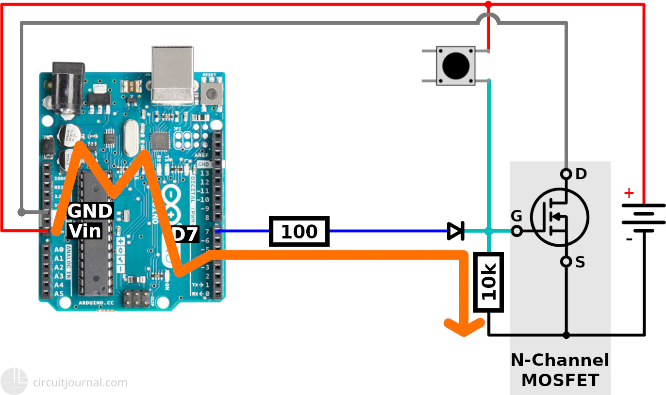
If this resistor has a very high value, then the current flowing through it would be minimal. But the voltage drop across it can be steep enough to turn the MOSFET partially ON. If the resistor has a small enough value so that the MOSFET is OFF, you will get higher current flowing directly through the resistor.
With a single MOSFET, you will never get your circuit to be completely OFF.
You need the second MOSFET to isolate the Arduino IO pin from the power source. If you use an N-Channel MOSFET to disconnect the positive wire, then you have to separate your IO pin from the positive output of the power source. If you are using a P-Channel MOSFET to disconnect the negative wire, then you have to isolate your IO pin from the negative output of the power source.
Leakage fixed by adding a P-Channel MOSFET on the D7 wire:
